Yagi Antenna Driven Element (G9C02)
The 2023-2027 General License question pool seeks the length of a Yagi antenna's driven element:
G9C02: What is the approximate length of the driven element of a Yagi antenna?
A. 1/4 wavelength
B. 1/2 wavelength
C. 3/4 wavelength
D. 1 wavelength
The Yagi antenna, also known as the Yagi-Uda antenna, was designed by Japanese inventors Shintaro Uda and Hidetsugu Yagi in 1926. Although Uda was the principle inventor with his colleague Yagi in a lesser role, the name Yagi became more associated with the antenna design due to Yagi’s filing of a patent without Uda’s name included, the subsequent transfer of that patent to the UK Marconi Company, and Yagi’s publication of the first English language description of the antenna design in 1928.

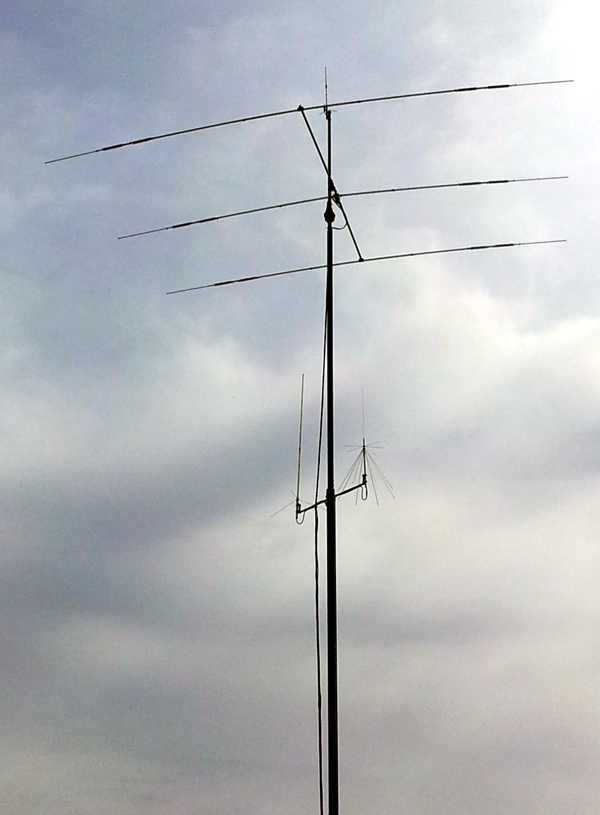
The Yagi antenna is a directional antenna, or beam antenna. It differs from the ideal isotropic emitter that theoretically radiates equally in all spherical directions from a point source, and it differs from the omni-directional antenna that radiates equally in all radial (horizontal) directions. A directional antenna such as the Yagi sacrifices radiated power in most directions to emit more powerfully in a single direction. The greater radiated power in the singular direction is called the main lobe of the antenna’s radiation pattern.
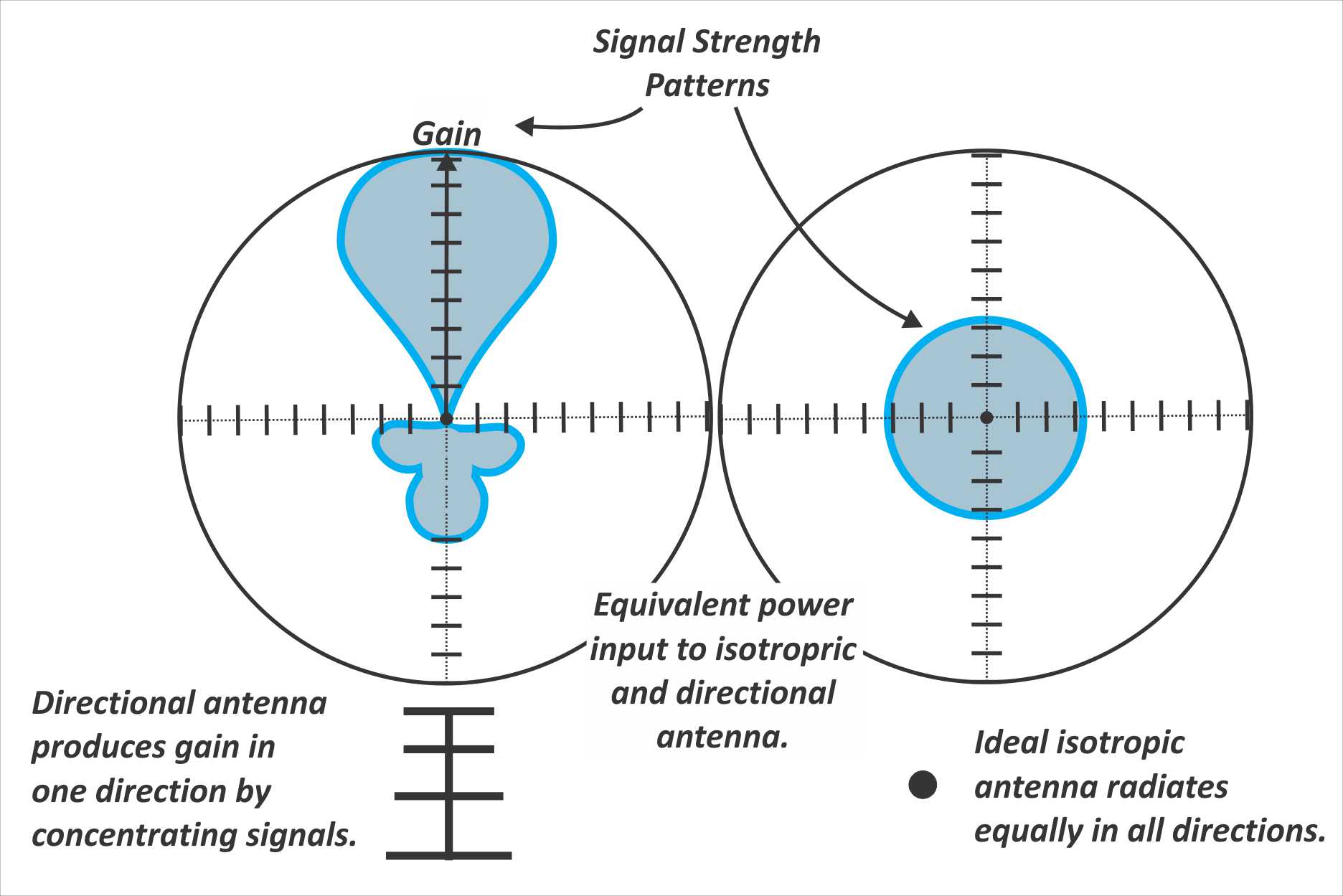
When a comparison is made between the directional antenna’s main lobe signal strength and a reference antenna such as the ideal isotropic radiator, the ratio resulting from the comparison is the directional antenna’s gain, usually expressed in decibels (dB). If the comparison antenna is the isotropic ideal case the comparison will usually be indicated with dBi. When a comparison is based upon the common half-wave dipole antenna reference instead, the gain is indicated as dBd.
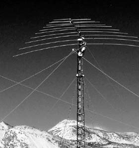
The Yagi directional antenna produces gain in its main lobe by careful positioning of parasitic elements. A parasitic element is an antenna element that is not directly energized by the transmitter via a feedline. A Yagi antenna will include a single driven element, the element to which the feedline is attached and that is energized during transmissions. Parasitic elements are positioned parallel to the driven element, both behind and in front of the driven element.
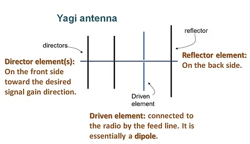
A parasitic element behind the driven element (opposite the direction of the main lobe of radiation) is called a reflector element. A parasitic element in front of the driven element (same direction as the main lobe) is called a director element. In addition to the driven element, a Yagi antenna may have a reflector only, or a reflector plus one or more director elements.
A parasitic element will be electrically energized by the RF radiation of the driven element during transmissions, and it will re-radiate RF due to this energizing. These parasitic elements are designed with specific lengths and spacing along the Yagi’s boom so that the combined radiated and re-radiated wavelengths cancel one another in the direction opposite the main lobe and reinforce one another in the forward direction. This wave reinforcement creates the increased power in the main lobe direction at the expense of rear and side direction radiation.
The spacing and number of parasitic elements in a Yagi help to determine the shape of the main lobe of radiation. Generally, a single reflector is implemented in a design, and as additional directors are added the radial angle of the main lobe will become narrower, increasing gain and directionality of the Yagi.
But, no matter the specifics of a particular Yagi design’s parasitic elements, it will have a single driven element that by itself is a commonly used antenna type. The Yagi employs a half-wave dipole as the driven element, and the parasitic elements manipulate and shape the radiated pattern of the half-wave dipole into the directional pattern of the main lobe. Of course, as the name indicates, a half-wave dipole is about one-half wavelength long.
The answer to General Class question G9C02, “What is the approximate length of the driven element of a Yagi antenna?” is “B. ½ wavelength.”
-- Stu WØSTU