Quadrature Modulation
In the world of amateur radio, we use a variety of modulation schemes to encode our voice or digital data onto an RF carrier. These modulation types include Continuous Wave (CW), Amplitude Modulation (AM), Frequency Modulation (FM), Phase Modulation (PM), and Single Sideband (SSB).
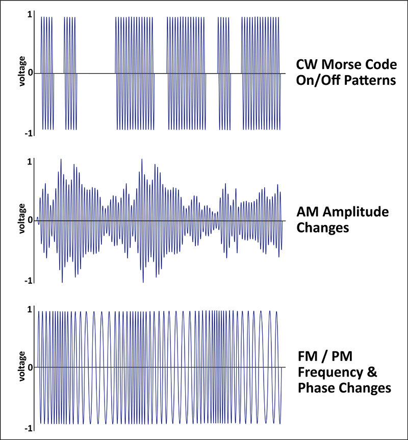
CW uses Morse Code to turn the RF carrier on and off, which is a simple form of controlling the amplitude of the signal. For voice communication, AM was developed to impose audio modulation onto the RF carrier by varying the amplitude of the carrier based on the modulating signal. Similarly, FM and PM modulate the frequency and phase of the carrier signal based on the modulating signal.
Like the analog modulation techniques, digital modulation is based on controlling the amplitude, phase, or frequency of the RF carrier. As digital modulation techniques became more common, it became useful to view modulation in a totally different way. Rather than showing the time domain representation of the RF carrier, the phasor diagram shown in Figure 2 shows just the carrier's amplitude and phase. The amplitude is represented by the length of the vector, and the phase is represented by the angle relative to the horizontal axis.
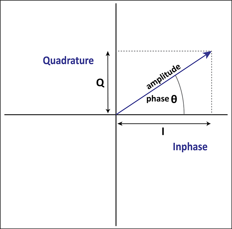
Graphically, we see that the amplitude and phase of the phasor can also be described using the horizontal axis (the inphase component, or I) and the vertical axis (the quadrature component, or Q). These two ways of defining the phasor are equivalent: we can work in terms of amplitude & phase or the inphase and quadrature (I/Q) coordinate components. This observation led to the development of versatile modulators that produce radio signals by controlling these inphase and quadrature components.
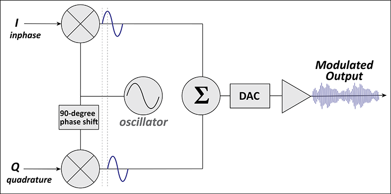
The quadrature modulator works by multiplying the inphase signal (I) by a local oscillator while the quadrature signal (Q) is multiplied by the same oscillator shifted by 90 degrees. This corresponds to and maintains the 90-degree relationship of I and Q shown in Figure 2. These two signals are then combined to produce the desired output - a signal of specified amplitude and phase. Again, the key idea here is that by controlling I and Q, the desired phasor shown in Figure 2 can be produced. The phase between the I and Q signals remains constant at 90 degrees but the amplitude of I and Q change based on the modulation being applied. I and Q can be produced based on analog modulation or some type of digital data stream.
As shown in Figure 3, the quadrature modulator is implemented using digital circuits and the I and Q signals are normally a stream of digital numbers representing the modulating signal. This could also be implemented using analog circuits but modern transceivers use digital. At the output of the modulator, a Digital-to-Analog Converter (DAC) converts the digital stream to an analog signal to be transmitted over the air, often with additional analog signal processing.
Binary Phase Shift Keying
Let's examine a simple digital modulation scheme used in PSK31 transmissions, called binary phase shift keying (BPSK). BPSK uses just two phases of the carrier to present either a logic 1 or 0. The amplitude remains constant.
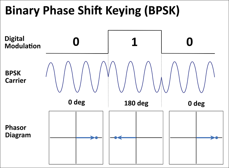
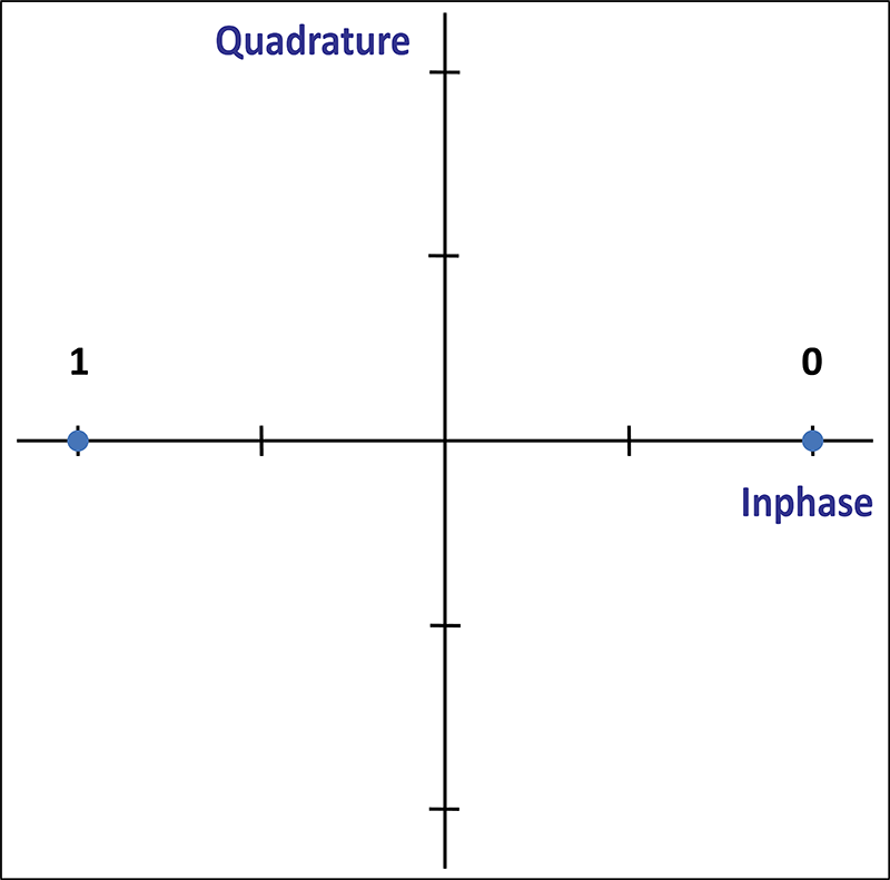
The phasor arrow is shown in Figure 4 for the two different states that the carrier takes on. Often, the arrow is left out of the diagram and a dot is plotted at the place where the arrow would point. Figure 5 shows such a diagram, called a constellation diagram.
Quadrature Phase Shift Keying
PSK31 has another mode available called QPSK31, which uses Quadrature Phase Shift Keying (QPSK). This modulation format also keeps the amplitude constant while changing the carrier into four distinct states.
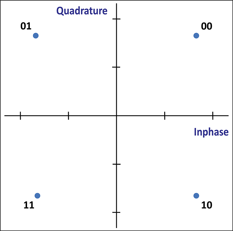
Because QPSK has four logic states available, these can be used to encode two bits of information. This doubles the digital throughput of the signal at the expense of degraded noise performance.
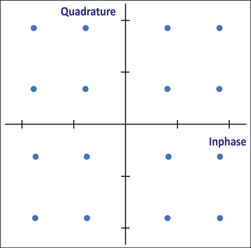
Although not commonly used for amateur radio, this approach can be expanded to implement Quadrature Amplitude Modulation (QAM), which varies both the amplitude and phase of the carrier. Figure 7 shows 16 QAM, which has sixteen states that can be represented by the carrier, each one representing four bits of information. Again, the digital throughput is increased but at the expense of degraded noise performance. Unlike BPSK and QPSK, the amplitude is modulated along with the phase to create these different states. Now you can see why these plots are called constellation diagrams as they start to look like a constellation of stars in the night sky.
In many high-bandwidth digital communications formats, higher-order QAM is used. For example, WiFi may use 64-QAM, 256-QAM, or 1024-QAM. You can imagine that the constellation diagrams for these modulation schemes get quite crowded, requiring precise signal generation and detection.
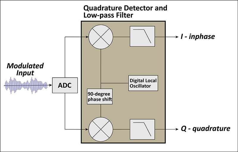
Quadrature Detector
A quadrature detector extracts the I and Q signals at the receiver. Figure 8 shows a typical configuration that is essentially the reverse of the modulator shown in Figure 3. A quadrature detector can be implemented using analog circuits but modern transceivers do this digitally. The incoming analog signal is converted to digital form by an analog-to-digital converter (ADC) and then fed into the quadrature detector. The detector multiplies the incoming signal by two oscillators offset in phase by 90 degrees to extract the I and Q information from the incoming signal. The output of the multiplier is normally followed by a lowpass filter to remove any high-order mixing products, leaving just the desired I and Q signals.
Legacy Analog Modulation
We have looked at how I/Q concepts support some of the common digital modulation formats. But what about the common analog modulation types such as AM, SSB, PM, and FM? For AM, it will be pretty simple to use the I and Q modulators to produce an amplitude-modulated signal. SSB is a form of AM so it is similar to the AM case. However, it will require some additional signal processing ahead of the quadrature modulator to eliminate one of the AM sidebands. Analog PM is implemented similarly to BPSK and QPSK, but with an analog (not digital) modulating signal. That is, I and Q are controlled to produce the desired phase shift in the phaser.
That leaves FM, which is a bit more elusive. You may recall that FM and PM are both forms of angle modulation. That is, they both affect the instantaneous phase angle of the carrier. The difference is that for a change in the modulating signal, PM does a one-time shift of the carrier phase on the current cycle only, while FM changes the frequency slightly which affects the phase of the current and future cycles. Well, it turns out that FM and PM are so closely related, that one can be derived from the other using digital signal processing. The net result is that FM signals can be supported as a variation of PM. Again, additional signal processing is required ahead of the modulator.
Software Defined Radio
This brings us to the concept of software-defined radio (SDR), which is a radio design approach that implements as much functionality as possible in software. Many of the traditional analog amplifiers, mixers, detectors, and modulators are implemented using software algorithms.
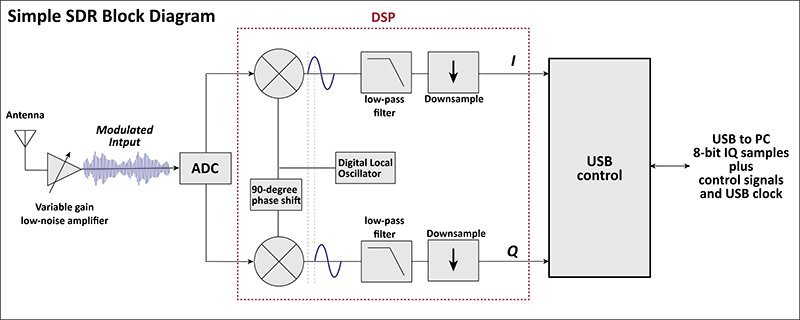
Figure 9 shows a simplified block diagram of a low-cost SDR receiver. This receiver has an analog-to-digital converter that directly samples the antenna's signal, after the low-noise amplifier. A Digital Signal Processing (DSP) section implements the quadrature demodulator, producing a digital stream of I/Q data. This I/Q data is transferred to an external computer via a USB interface. Most of the signal processing and detection is done in the computer. Because the I/Q data contains all of the signal information, almost any type of signal can be demodulated using the computer software. This is why it is called "software-defined", indicating a high degree of flexibility. Figure 9 shows just a receiver but a similar approach can also be used to create a software-defined transmitter.
Many but not all ham transceivers are implemented using SDR technology. However, the trend line is clear so we will see the use of this design approach increase which will provide all sorts of new radio capabilities at a reasonable cost.