SSB Receive Filter Bandwidth
Technician question pool item T4B09 (2018-2022) raises the issue of filters for receiving single sideband signals:
T4B09: Which of the following is an appropriate receive filter bandwidth for minimizing noise and interference for SSB reception?
A. 500 Hz
B. 1000 Hz
C. 2400 Hz
D. 5000 Hz
Let's carefully examine this question in context and content, as it gets at some fundamental characteristics of receiver operations.
A radio receiver is really quite a marvelous device, and we operators ask a lot of our receivers. Our environment is awash in radio frequency emissions, some being noise and some intentional transmissions carrying information by various modulation methods such as FM, AM, SSB, CW, or others. The task we expect from our receiver is to be able to cut through the RF cacophony and detect just the singular signal that we desire to hear. It is analogous to finding the proverbial needle in the haystack, albeit with a bit of operator search guidance.
The ability of a receiver to discriminate between multiple signals is its selectivity. That is, a receiver selects one signal in the band among other signals of frequencies immediately adjacent in the band. The receiver filter bandwidth is a primary factor in determining the receiver selectivity. The receive filter bandwidth determines the range of frequencies that will be allowed to pass through the demodulation sequence and ultimately drive an audio signal to be heard.
Let’s review a couple of basic concepts about RF signals and then we’ll dive into the heart of this question. First, any RF signal uses a range of frequencies, typically a contiguous range. For instance, the single sideband signal uses about 3000 Hz (3 kHz) of frequency range, or bandwidth. With a SSB phone transmission, the 3 kHz of RF bandwidth carries the information of voice audio signals to be received and transformed back into sound by a receiver. We can represent the 3 kHz of RF frequencies of various amplitude (power) with a spectrum, like this.
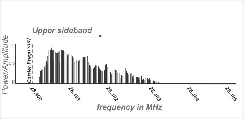
The carrier frequency -- the value that shows up on your receiver display when you tune -- can be considered a reference point that tells the receiver where to find this 3 kHz band of signals that you wish to demodulate into audio. With SSB, no signal is actually transmitted exactly on the carrier frequency value, but the receiver knows to look across a band 3 kHz higher (upper sideband, USB) or lower (lower sideband, LSB) in frequency than the tuned carrier value to find the RF band to receive and demodulate.
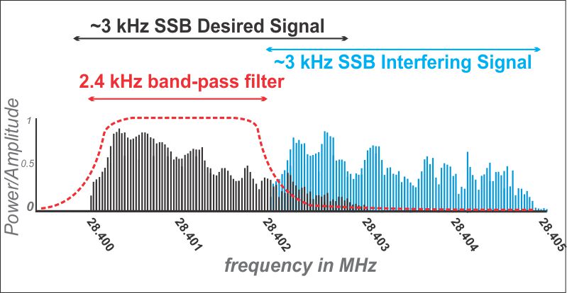
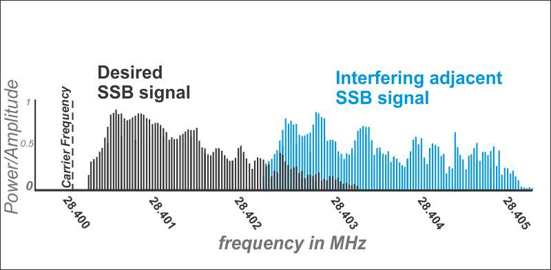
Imagine how the receive spectrum would appear if another SSB signal began to partially interpose itself in the selected receive band. In this image, the interfering adjacent signal band represented in blue overlaps with the higher frequency end of the USB signal that you actually wish to receive (represented in black). This situation will cause interference in your receive audio, as the lower frequencies of the interfering signal (blue) will be demodulated by the receiver along with the desired band’s higher end frequencies (black). The result is that your receive audio will contain noise that, at least in part, masks the desired audio signal you wish to hear.
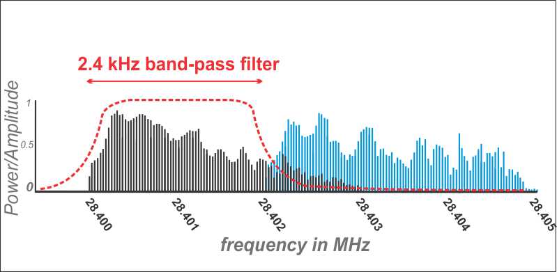
Now enters the concept of selectivity and the mighty receive filter bandwidth to save the day! You can select a filter that is somewhat narrower in bandwidth than the desired signal bandwidth and position it to cut out that higher end interference from the blue signal. The red dashed line illustrates the “passed band” by the receive filter -- only the signal within the filter width is allowed to continue in the demodulation stream of the receiver. The filter will attenuate the power of the interfering blue signals that reside outside of the filter's spectral width. That pesky interfering noise from the adjacent signal in your audio fades away!

“But,” you now ask, “aren’t my desired signal frequencies also being attenuated by this filter?” Yes, necessarily in this scenario the higher end of the desired receive signal is also attenuated, but plenty of bandwidth is still available to produce intelligible audio from the desired RF signal. The quality of the audio may be slightly reduced, but the even more quality-killing noise has been eliminated, allowing you to understand the now-slightly-narrower desired signal’s audio.
So, if you have a SSB receiver with multiple receive bandwidth choices, you have an advantage by selecting a bandwidth that matches the bandwidth of the mode (SSB in this case) and that optimizes the ratio of desired signal to undesired noise or interference. With SSB you will maintain a clearly intelligible audio signal with about 2400 Hz, or 2.4 kHz, of bandwidth. This is a good bandwidth match for SSB reception that will help filter out immediately adjacent or slightly interfering signals on the band.
The answer to Technician Class question T4B09, “Which of the following is an appropriate receive filter bandwidth for minimizing noise and interference for SSB reception” is “C. 2400 Hz.”
--Stu WØSTU