Search Results
127 results found with an empty search
- Quadrature Modulation
In the world of amateur radio, we use a variety of modulation schemes to encode our voice or digital data onto an RF carrier. These modulation types include Continuous Wave (CW), Amplitude Modulation (AM), Frequency Modulation (FM), Phase Modulation (PM), and Single Sideband (SSB). CW uses Morse Code to turn the RF carrier on and off, which is a simple form of controlling the amplitude of the signal. For voice communication, AM was developed to impose audio modulation onto the RF carrier by varying the amplitude of the carrier based on the modulating signal. Similarly, FM and PM modulate the frequency and phase of the carrier signal based on the modulating signal. Like the analog modulation techniques, digital modulation is based on controlling the amplitude, phase, or frequency of the RF carrier. As digital modulation techniques became more common, it became useful to view modulation in a totally different way. Rather than showing the time domain representation of the RF carrier, the phasor diagram shown in Figure 2 shows just the carrier's amplitude and phase. The amplitude is represented by the length of the vector, and the phase is represented by the angle relative to the horizontal axis. Graphically, we see that the amplitude and phase of the phasor can also be described using the horizontal axis (the inphase component, or I ) and the vertical axis (the quadrature component, or Q ). These two ways of defining the phasor are equivalent: we can work in terms of amplitude & phase or the inphase and quadrature (I/Q) coordinate components. This observation led to the development of versatile modulators that produce radio signals by controlling these inphase and quadrature components. The quadrature modulator works by multiplying the inphase signal (I) by a local oscillator while the quadrature signal (Q) is multiplied by the same oscillator shifted by 90 degrees. This corresponds to and maintains the 90-degree relationship of I and Q shown in Figure 2. These two signals are then combined to produce the desired output - a signal of specified amplitude and phase. Again, the key idea here is that by controlling I and Q, the desired phasor shown in Figure 2 can be produced. The phase between the I and Q signals remains constant at 90 degrees but the amplitude of I and Q change based on the modulation being applied. I and Q can be produced based on analog modulation or some type of digital data stream. As shown in Figure 3, the quadrature modulator is implemented using digital circuits and the I and Q signals are normally a stream of digital numbers representing the modulating signal. This could also be implemented using analog circuits but modern transceivers use digital. At the output of the modulator, a Digital-to-Analog Converter (DAC) converts the digital stream to an analog signal to be transmitted over the air, often with additional analog signal processing. Binary Phase Shift Keying Let's examine a simple digital modulation scheme used in PSK31 transmissions, called binary phase shift keying (BPSK). BPSK uses just two phases of the carrier to present either a logic 1 or 0. The amplitude remains constant. The phasor arrow is shown in Figure 4 for the two different states that the carrier takes on. Often, the arrow is left out of the diagram and a dot is plotted at the place where the arrow would point. Figure 5 shows such a diagram, called a constellation diagram . Quadrature Phase Shift Keying PSK31 has another mode available called QPSK31, which uses Quadrature Phase Shift Keying (QPSK) . This modulation format also keeps the amplitude constant while changing the carrier into four distinct states. Because QPSK has four logic states available, these can be used to encode two bits of information. This doubles the digital throughput of the signal at the expense of degraded noise performance. Although not commonly used for amateur radio, this approach can be expanded to implement Quadrature Amplitude Modulation (QAM), which varies both the amplitude and phase of the carrier. Figure 7 shows 16 QAM, which has sixteen states that can be represented by the carrier, each one representing four bits of information. Again, the digital throughput is increased but at the expense of degraded noise performance. Unlike BPSK and QPSK, the amplitude is modulated along with the phase to create these different states. Now you can see why these plots are called constellation diagrams as they start to look like a constellation of stars in the night sky. In many high-bandwidth digital communications formats, higher-order QAM is used. For example, WiFi may use 64-QAM, 256-QAM, or 1024-QAM. You can imagine that the constellation diagrams for these modulation schemes get quite crowded, requiring precise signal generation and detection. Quadrature Detector A quadrature detector extracts the I and Q signals at the receiver. Figure 8 shows a typical configuration that is essentially the reverse of the modulator shown in Figure 3. A quadrature detector can be implemented using analog circuits but modern transceivers do this digitally. The incoming analog signal is converted to digital form by an analog-to-digital converter (ADC) and then fed into the quadrature detector. The detector multiplies the incoming signal by two oscillators offset in phase by 90 degrees to extract the I and Q information from the incoming signal. The output of the multiplier is normally followed by a lowpass filter to remove any high-order mixing products, leaving just the desired I and Q signals. Legacy Analog Modulation We have looked at how I/Q concepts support some of the common digital modulation formats. But what about the common analog modulation types such as AM, SSB, PM, and FM? For AM, it will be pretty simple to use the I and Q modulators to produce an amplitude-modulated signal. SSB is a form of AM so it is similar to the AM case. However, it will require some additional signal processing ahead of the quadrature modulator to eliminate one of the AM sidebands. Analog PM is implemented similarly to BPSK and QPSK, but with an analog (not digital) modulating signal. That is, I and Q are controlled to produce the desired phase shift in the phaser. That leaves FM, which is a bit more elusive. You may recall that FM and PM are both forms of angle modulation . That is, they both affect the instantaneous phase angle of the carrier. The difference is that for a change in the modulating signal, PM does a one-time shift of the carrier phase on the current cycle only, while FM changes the frequency slightly which affects the phase of the current and future cycles. Well, it turns out that FM and PM are so closely related, that one can be derived from the other using digital signal processing. The net result is that FM signals can be supported as a variation of PM. Again, additional signal processing is required ahead of the modulator. Software Defined Radio This brings us to the concept of software-defined radio (SDR) , which is a radio design approach that implements as much functionality as possible in software. Many of the traditional analog amplifiers, mixers, detectors, and modulators are implemented using software algorithms. Figure 9 shows a simplified block diagram of a low-cost SDR receiver. This receiver has an analog-to-digital converter that directly samples the antenna's signal, after the low-noise amplifier. A Digital Signal Processing (DSP) section implements the quadrature demodulator, producing a digital stream of I/Q data. This I/Q data is transferred to an external computer via a USB interface. Most of the signal processing and detection is done in the computer. Because the I/Q data contains all of the signal information, almost any type of signal can be demodulated using the computer software. This is why it is called "software-defined", indicating a high degree of flexibility. Figure 9 shows just a receiver but a similar approach can also be used to create a software-defined transmitter. Many but not all ham transceivers are implemented using SDR technology. However, the trend line is clear so we will see the use of this design approach increase which will provide all sorts of new radio capabilities at a reasonable cost.
- What's That Connector on My HT?
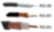
All ham radio handheld transceivers are shipped standard with an electrically-short monopole antennas, more commonly called rubber duck antennas . I usually refer to this type of antenna as a very convenient crummy antenna. A rubber duck is handy when carrying your HT, adequate for many uses but not as efficient as a full-size antenna. It is nice to be able to attach a higher performance antenna when needed, such as a longer handheld antenna or a mobile mag-mount antenna. The BNC (Bayonet Neill–Concelman) connector is used in a wide variety of electronic products and it used to be the standard connector for HTs. It is particularly convenient due to its “twist and lock” operation —-easy on, easy off. As handheld transceivers became more compact, the BNC was largely replaced with the much smaller SMA (SubMiniature version A) connector. The BNC (Bayonet Neill–Concelman) connector is used in a wide variety of electronic products and it used to be the standard connector for HTs. It is particularly convenient due to its “twist and lock” operation —-easy on, easy off. As handheld transceivers became more compact, the BNC was largely replaced with the much smaller SMA (SubMiniature version A) connector . For example, the Yaesu FT-60 uses a female SMA connector for the antenna connection. Since Yaesu, Icom and Kenwood all use this connector, I’d say this is the standard approach for the amateur radio market. A few manufacturers have decided to use the male SMA connector as the antenna connection for their handheld radios. I suspect that these manufacturers are following the lead of commercial radio manufacturers (e.g., Motorola) who also use the male connector. This approach seems to be popular with the Chinese manufacturers (Wouxun, Baofeng, etc.) Either gender of SMA connector is just fine but you’ll want to be aware of which one your radio uses when buying accessories for your HT. Sometimes hams adapt these SMA connectors back to the good old BNC, to connect existing BNC cables or antennas. The adapter in the center is a common adapter for cable use but arguably mechanically weak for adapting HT antennas. The adapter on the left adapts BNC antennas to an HT with a male SMA connector and fits snugly on the top of the HT, providing mechanical support. Similarly, the adapter on the right adapts BNC antennas to an HT with a female SMA connector. I hope this helps you sort out the different connectors on your radio. You’ve got to get connected if you’re going to connect on the airwaves! Thanks for stopping by! 73, Bob K0NR
- How Many Antennas Do I Need?
Recently a student in our Technician License Class realized that it may take quite a few antennas to cover all of the available ham bands. He asked, “So how many antennas do I need?” Of course, my answer was “you can never have too many antennas.” This is a very valid question. Radio amateurs have so many bands available to them, it does present a challenge to figure out the antenna situation. Someone recently said to me, “getting the radio is the easy part — figuring out the antennas is the real challenge.” So true. A new Technician often decides to just focus on VHF/UHF with an emphasis on FM simplex and repeater operation. The focus of this article is broader than that, with the addition of HF operation. Keep in mind that a Technician Class license gives you access to all of the VHF/UHF bands and a relatively small slice of the HF bands (10 meter phone plus 80m, 40m, 15m and 10m CW). The General Class license provides greatly expanded privileges on HF. Imagine that you just bought one of those “do everything rigs” that cover all of the HF bands, 6m, 2m and 70 cm (e.g., Yaesu FT-857, FT-991, Kenwood TS-2000, or Icom IC-7100). That’s a lot of spectrum to cover and no single antenna will do it all efficiently. A basic antenna setup for such a station is to use a dualband VHF/UHF antenna to cover 2m and 70cm, along with a multi-band HF antenna. This won’t actually result in an antenna system that covers all of the ham bands, but it can be a good start. The dual-band VHF/UHF antenna could be a Diamond X-50A , a Comet GP-3 , or similar antenna. Another popular design is the Arrow Open Stub J-Pole antenna . These antennas are vertically polarized, covering basic 2m and 70 cm simplex and repeater operating. They won’t do a good job with weak-signal SSB or CW operating, where horizontal polarization is preferred. Some folks may argue for just putting up a single-band antenna for 2m only, which is the most popular VHF band. For operating on the HF bands, you’ll want an efficient antenna that covers multiple bands. You could put up single-band antennas for every band, but that gets complicated and typically results lots of antennas and lots of cable runs back to the ham shack. Focusing on the new ham, it makes sense to go for a multiband antenna and keep the number of individual coaxial cable runs to just a couple. The first question that pops up is “which bands?” Well, that depends . My biases are towards the higher bands (20m and up) because I like to work other countries around the world during daylight hours. If you are more interested in North American contacts, especially in the evening hours, you might want to cover the 40m and 80m bands. For a new ham, this may be difficult to figure out, until you get some experience and discover your preferred ham bands. So, a good compromise for the new HF operator is a multiband antenna that allows operations on a couple of higher bands (perhaps 20-meters, 15-meters, and/or 10-meters), and operation on at least one lower band (perhaps 40-meters and/or 80-meters). Some reasonably inexpensive commercial options with such band allowances are readily available as horizontal wire fan dipoles or trap dipoles. Let’s consider these options: Fan Dipole (also known as a parallel dipole) – This is a half-wave dipole with additional elements added to cover additional bands. While there is some interaction between the different dipole elements, they are normally fed by a common coaxial cable, avoiding the need for multiple cable runs. Trap Dipole – This antenna uses tuned circuits (“traps”) to enable a single dipole to operate on multiple bands. The dipole length is determined by the lowest frequency band and the traps are used to electrically shorten the dipole for higher bands. Trap antennas can usually be designed to work well with two or three different HF bands, and designs combining fan and trap dipole features can provide more, with some trade-offs in efficiency and performance. End Fed Half Wave (multiband) – This half-wave antenna is similar to a dipole but the coaxial cable is connected to one end of the half wave wire, allowed easier mounting than the typical center-fed dipole. A well designed matching transformer at the end feed point facilitates this antenna configuration. Multiband versions of this antenna exist and are a convenient way to enable several bands at once. The popular Vibroplex Par EndFedZ ® product line offers several multiband options. Multiband vertical – Quite a few different vertical antenna designs support multiple bands. For example, see the or R9, GAP Challenger DX, Butternut HF9V and the Hustler 4BTV . When considering a vertical antenna, pay attention to whether the design requires ground radials to be installed. Nothing wrong with them, but radials can be critical to achieving efficient antenna performance. If you have restrictive covenants, you might consider a vertical antenna that is also a flag pole (really!). Take a look at ZeroFive Antennas for examples. Antenna Tuners – When trying to cover lots of bands with just a few antennas, an antenna tuner will be really handy. This may be built into your radio or it may be a separate box inserted into the feedline between the transmitter and antenna. An antenna tuner does not actually “tune your antenna” but it will tweak up the SWR of the antenna and allow it to be used across a broader range of frequencies. It also will keep your transmitter happily perceiving a nice 50-ohm feedline impedance that circumvents automatic power reductions that come with high SWR from an impedance mismatch. Other Bands and Modes I’ve focused on the most popular ham bands, but there are many other frequencies to consider. The 6-meter band is a lot of fun and is accessible to Technicians. Most of the time, this band is good for local communication but it often opens up for over-the-horizon skip by sporadic-e propagation , especially during the summer months. Some of the multiband HF antennas mentioned above also cover 6 meters, or you can put up a separate 6m dipole to get started. The more serious 6m operators use a Yagi antenna to produce gain and a big signal. In most station configurations, a separate 6-meter antenna will dictate another dedicated coaxial cable run. Another fun mode is 2m single sideband (SSB) , the workhorse band for weak-signal VHF. You’ll need a horizontally-polarized 2-meter antenna, preferably with some gain. The most common antenna used is a Yagi with many elements, such as the M2 2M9SSB antenna or the portable Arrow models . So, How Many? – You can make a lot of contacts and construct a superb HF to UHF station with just two quite simple antennas. The VHF/UHF vertical dual-band antenna paired with a multiband horizontal wire dipole is a cost-efficient, easy-to-erect combination providing FM simplex and repeater ops for local communications as well as long-distance HF skip on several bands. It’s a very good way to start. Putting together an antenna system can seem like an overwhelming task for the beginner, so don’t get too freaked out about it. The main thing is to get something usable up in the air and make some contacts. Over time, you will probably add or change your antennas to get just what you want. That is part of the fun of amateur radio. Bob K0NR
- dBi vs. dBd (G9C04)
The 2023-2027 General License question pool wants you do differentiate between dBi and dBd when it comes to antenna gain: G9C04: How does antenna gain stated in dBi compare to gain stated in dBd for the same antenna? A. dBi gain figures are 2.15 dB lower than dBd gain figures B. dBi gain figures are 2.15 dB higher than dBd gain figures C. dBi gain figures are the same as the square root of dBd gain figures multiplied by 2.15 D. dBi gain figures are the reciprocal of dBd gain figures + 2.15 dB Antenna gain means that an antenna produces increased signal strength is a particular direction at the expense of signal strength in other directions. Usually, antenna gain is expressed as a comparison with a reference antenna. For instance, a directional antenna such as a 3-element Yagi may provide signal strength in its forward direction roughly 7 dB to 9 dB over common reference antennas that radiate more equally in all directions. This question is all about those common reference antennas and the nature of gain comparisons. One of the common antenna gain references is the theoretical point source antenna that radiates equally in all spherical directions. Uniformity in all orientations is called isotropy , and this common reference is called the isotropic antenna. When an antenna’s signal strength is compared to the isotropic antenna, any gain in signal strength stated in decibels is denoted with a lower case letter ‘i’ following the unit dB. Hence, dBi. Another common reference antenna is the simple free space dipole antenna. The “free space” terminology means that the dipole reference is the theoretical performance of the dipole if it had no other objects near it, including the earth. The height of a dipole above the earth dramatically affects its radiation patterns, as can other objects (especially conductive objects) near the dipole. But a dipole in free space has none of these RF coupling impacts from other objects and its radiation pattern is a nice, theoretical, toroidal pattern emanating radially from the axis of the dipole radiator. When an antenna’s signal strength is compared to the theoretical free space dipole performance, any gain in signal strength stated in decibels is denoted with a lower case letter ‘d’ following the unit dB. Hence, dBd. Compare the free space dipole pattern with the isotropic antenna pattern. Notice that the dipole’s pattern produces the greatest signal strength broadside, or radially, to its radiator axis. The increased signal strength in the radial directions comes at the expense of signal strength out the ends of the dipole radiator. Thus, when compared to the isotropic antenna the dipole exhibits gain is its radial directions. We may state the gain of the dipole as compared to the isotropic antenna in units of dB. Further, since this antenna comparison is using the isotropic case as the basis of performance, we should denote the gain units as dBi. The free space dipole exhibits gain in the radial directions over the isotropic antenna of 2.15 dBi. This is a comparison of one theoretical antenna model (free space dipole) to another theoretical antenna model (isotropic). Now, let’s apply these facts to this specific question pool item. When you purchase an antenna the gain will often be printed on the packaging or in literature. Let’s use a vertical omnidirectional antenna as an example -- this antenna radiates equally in all radial horizontal directions, but not so much in the vertical directions up or down. Here is the packaging for a dual band vertical that I use in my attic. Notice the gain figures are 4.5 dB for the 2-meter band and 7.2 dB for the 70-centimeter band. Ominously missing is the reference antenna denotation. (Shame!) But rest assured, it is dBi. In other words, the antenna produces those stated gain values in the horizontal radial directions as compared to the theoretical isotropic radiator. Consider what would happen to the stated gain figures for this antenna if they were compared to the dipole reference instead. The dipole already has 2.15 dB gain over the isotropic reference. So, the gain figures must be reduced by 2.15 dB when the higher performing dipole reference is used for comparison. These stated dBi gain figures are 2.15 dB higher than equivalent dBd gain figures. Gain stated in dBi is always a larger number than gain stated in dBd, making an antenna product’s performance sound more impressive, and that’s one reason why most antenna products state gain in dBi even though comparison to a simple dipole is usually a more meaningful and practical comparison. The answer to this General Class question G9C04, “How does antenna gain stated in dBi compare to gain stated in dBd for the same antenna?” is “B. dBi gain figures are 2.15 dB higher than dBd gain figures.” -- Stu WØSTU
- FM Repeaters -- An Introduction
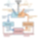
Operating on VHF/UHF FM repeaters is one of the most popular activities in amateur radio. For the new ham, FM repeater ops are often the first and most common on-air experiences, but accessing repeaters also represents a significant initial vexation for the new ham to overcome. Mastering the integrated concepts of frequency pairs, tones or other squelch methods, transceiver channel programming, and repeater on-air protocols is the first significant operational challenge that many hams will encounter in their new hobby. This article introduces fundamental concepts of FM repeater operations for the new ham and depicts a high level view of typical FM phone repeater anatomy and functioning. The goal is to demystify repeaters and help the newly licensed Technician overcome any initial bewilderment about repeaters. Let’s get off to a great start in ham radio with solid footing in repeaters. Repeater Basics: As the name implies, an FM repeater repeats your radio signal. It is just an amateur radio station that has been designed for the special purpose of retransmitting your signal instantaneously as it is received. Typically, an FM repeater station will be located in a high position, perhaps on a hill or mountain, or on a sizable tower or building. A repeater station may also retransmit with higher power than an operator uses with a handheld transceiver or other station transmitting to the repeater. As a result, the FM repeater’s relay of your signal is transmitted over a much broader area than you can achieve with your station alone. The fundamental benefit is that operators who are geographically separated significant distances can use the repeater to achieve radio contact when simplex operations are not feasible or practical due to the separation or terrain. Further, because an FM repeater uses published, unchanging frequencies, it is a convenient way for amateurs within its reach to convene on the air. Groups of amateur operators will use a repeater to operate nets , on-air meetings at prearranged times, usually for a specific purpose or topic of interest. Nets on repeaters may also be convened by amateur radio emergency response agencies to coordinate emergency aid efforts across a broad area within the repeater’s range. While multiple types of repeaters are operated by amateurs around the world, the most common type is the FM voice repeater using VHF or UHF frequencies. But repeaters may be operated using single sideband mode, digital modes, and HF frequencies, as well. In this article we will refer almost exclusively to those most common VHF/UHF FM repeaters for voice or phone mode. FM Repeater Operation: What do you need to do to use an FM repeater with your transceiver? Let’s consider the practical aspects of repeater operation using an example. Then we can build on these basics for a more thorough understanding of repeater functions. As an FM repeater receives your signal it must retransmit it on a different frequency. It cannot retransmit on the same frequency that you are using to reach the repeater – that would cause a feedback loop in which the repeater’s receiver would “hear itself” transmitting and then try to retransmit its own output signal. Trouble lies there. Frequency Pairs: Instead, repeaters use frequency pairs : One frequency is used to receive signals from ham station operators and another frequency is used to retransmit those received signals. Consider the UHF 70-centimeter band example in the graphic below. Each calling station transmits to the repeater using 442.725 MHz. Each station monitors the repeater using a frequency of 447.725 MHz. When the pedestrian HT radio operator transmits his signal (red arrows), the 442.725 MHz transmission is received by the repeater and it retransmits the signal on 447.725 MHz to be received by any other stations monitoring that repeater frequency. Any other station, such as the SUV mobile station (blue arrows) operates exactly the same way, transmitting on the lower frequency 442.725 MHz and listening on the higher 447.725 MHz frequency. These paired frequencies are often referred to as the “listen frequency” and the “talk frequency,” as considered from the calling operators’ perspective. Of course, different FM repeaters will use different frequency pairs and entirely different amateur bands, and this is just one frequency pair example from the 70-centimeter band. Offsets: Notice in our example that the difference between the listen frequency (447.725 MHz) and the talk frequency (442.725 MHz) is exactly 5 MHz. This difference between the repeater’s paired frequencies is called the offset or shift . Standard values for repeater offsets are established for each band, but these are only recommendations. Most repeaters follow the standard offsets as follows, but not all: Amateur Band Standard Offset Example Pair, Listen/Talk (MHz) 2-meter band 0.6 MHz (600 kHz) 147.345 / 147.945 (+) 70-centimeter band 5 MHz 449.125 / 444.125 (-) 1.25-meter band 1.6 MHz 224.940 / 223.340 (-) A frequency pair offset may be positive (+) or negative (-). That is, the talk frequency may be higher (+) or lower (-) than the listen frequency. The shift, positive or negative, is always determined as: Talk Frequency - Listen Frequency = Offset So, in our picture example above the repeater has a negative offset since the talk frequency is lower than the listen frequency. In the 2-meter band example in the table above the offset is positive since the talk frequency (147.945 MHz) is higher than the listen frequency (147.345 MHz). Transceiver Channels: At this point you may be wondering how you can readily operate your radio this way, shifting between listen and talk frequencies during an on-air conversation. It is simple, really. You will program a memory channel into your radio for a specific repeater through which you wish to communicate. Just like the FM repeater, your programmed memory channel will use two different frequencies, the repeater's listen and talk pair. When you tune to your programmed memory channel for the repeater your radio will automatically shift to the transmit frequency any time you push-to-talk, and it will automatically shift back to the listen frequency when you release the PTT key. So, radio communications through a repeater become just as easy as simplex contacts directly between two stations. Squelch Tones: Many repeaters utilize one additional wrinkle that you will need to include in your channel programming or the repeater will ignore your transmissions. A repeater often will use a special method of squelch in its receiver, and you must include the correct squelch information in your transmission to open the squelch of the repeater. One of the most common methods of repeater squelch employed in the US is a low frequency audio tone that is transmitted continuously along with your voice signal. If this continuous tone is not transmitted in your signal, the repeater’s squelch will not be opened and the repeater will not receive your transmission. This squelch method is known as the Continuous Tone Coded Squelch System, or CTCSS. (Sometimes this is also referred to as PL tones by hams, a Motorola trademark referring to “private line,” but it is not at all private.) A repeater will use a single established tone from a set of standard frequencies. When you program a channel into your radio for a specific repeater you must select the appropriate CTCSS tone used by the repeater and ensure your CTCSS transmit function is activated for the channel. When properly accomplished, your transmission will automatically include the selected continuous tone and the repeater will happily receive your signal. Repeaters filter out the CTCSS tone from retransmissions so that it is not heard as audio by receiving stations. Standard set of CTCSS tones (Hz) 67.0 82.5 100.0 123.0 151.4 186.2 225.7 69.3 85.4 103.5 127.3 156.7 192.8 229.1 71.9 88.5 107.2 131.8 162.2 203.5 233.6 74.4 91.5 110.9 136.5 167.9 206.5 241.8 77.0 94.8 114.8 141.3 173.8 210.7 250.3 79.7 97.4 118.8 146.2 179.9 218.1 254.1 Other methods of repeater squelch are sometimes implemented, although in the US CTCSS is the most common. Digital-Coded Squelch (DCS) uses a stream of digital data or codes to open the repeater squelch, while simple carrier squelch opens the squelch any time an RF carrier signal is detected (i.e., no special squelch tones or codes). Repeater Coordination: You can probably imagine that if two FM repeaters implementing the same frequency pair have transmission ranges that overlap, a significant interference issue arises. For example, a single operator in range of both repeaters could cause both repeaters to activate when only one activation is intended, possibly interfering with ongoing communications on the repeater of accidental activation. Since repeaters tend to have significant range it is important to ensure they are coordinated to avoid mutual interference. Consideration of repeater geographic separation, transmission power, as well as the use of different frequency pairs and careful selection of CTCSS or other squelch methods helps to avoid repeater conflicts. Regional frequency coordinators are selected by operators and organizations whose stations are eligible to be repeaters. The coordinator recommends repeater pair frequencies and other station parameters to help avoid interference. The frequency coordinator may itself be a group or organization comprised of repeater operators or club representatives. On-Air Protocols: Be aware that every FM repeater will have a community of regular operators who use it, and these communities tend to develop something of a personality for the repeater. Some repeaters may have policies or rules established for its use. For example, many wide area repeaters (repeaters that reach over a very wide range) may have a policy of priority-only traffic, or a “no rag chewing” policy. That is, the repeater operators wish to keep the repeater available for long-range communications of a more important nature than checking up on the health of your friend’s cat in the midst of an hour-long, idle chit-chat QSO. Still, other repeaters may be designated specifically for extended rag chewing, yucking it up, and generally having fun on the air within the regulations of FCC Part 97. It is a good idea to monitor a repeater for a while, contact the repeater operator, look for information about the repeater online or inquire with other hams before using a repeater extensively. Get to know the repeater’s personality. Many FM repeaters will host regular nets at designated times. Become familiar with the repeater’s schedule of events and plan to avoid use during scheduled nets or other on-air events. If you are engaged in a QSO and another operator breaks in to notify you that a net will soon be starting on the repeater, graciously yield your privilege to the frequency and perhaps take part in the net if it is of interest to you. If you wish to make known your presence on an FM repeater, perhaps to pick up a casual contact, simply state your call sign on the air – no other elaborations required. Many operators using mobile stations will tack on “mobile” to their call sign to clarify that they are not at their home station. Hams operating from a stationary location other than their registered home station will often add the term “portable” to their call sign. But “CQ” (calling any station) is rarely used on FM repeaters, and most operators will skip the use of phonetics as well due to the clear, low noise character typical of most FM repeaters. You may hear courtesy tones on a repeater that indicate the end of a repeated transmission, and these tones substitute for the use of terms like “over” at the end of a transmission. You will also typically hear the repeater identify itself with either Morse Code tone patterns or by recorded or electronic voice ID at least every 10 minutes. A good rule of thumb during an extended QSO is to identify your station whenever the repeater identifies itself, helping you to keep with the 10 minute identification rule of the FCC Part 97. For most casual conversation via repeater, common language and common courtesy is the norm. You will hear a few Q signals thrown in by operators on repeaters, so it pays to be familiar with the most commonly used Q signals such as QSO, QSY, QRM, QSL, and others. But the beginner will have little trouble fitting in immediately on most repeaters. However, when a tactical net is convened on an FM repeater, perhaps for public event communications operations or an emergency communications tactical net, the casual nature of on-air communication is significantly reduced, especially if the net is busy with traffic. During a tactical net the transmissions will be succinct and to the point, with specific protocols implemented by a net control station. So, find the FM repeaters in your area, monitor each for a while, and do your research. Get your radio channels programmed and get on the air with one or more repeaters that suit your needs and your preferences. How Repeaters Work: Understanding a bit about how FM repeaters are designed and how they work will improve your understanding of their on-air operations. Repeaters are not very different from other transceivers, but a few specialized components have been added to affect the repeat function via frequency pairs and to automate the repeater control. Let’s take a surface glance under the hood of a typical FM repeater. Follow along in the simplified block diagram below of the most basic repeater architecture. Duplexer: Inbound RF signals from a transmitting station are received by the repeater antenna and directed to a component called the duplexer . A duplexer is a device that allows a single antenna to be used simultaneously for transmitting and receiving two different frequencies. Why is this needed, you ask? Necessarily, a repeater must receive and transmit at the same time, albeit on two different frequencies. When a high power transmitter and a receiver of great sensitivity operate in the same band near one another in frequency, the transmitter’s signal will overwhelm the receiver even though the tuned frequencies for transmit and receive are not identical. A typical receiver system cannot adequately reject , or filter out, the powerful blast of the transmitter. As a result, the repeater’s strong re-transmitted signal will mask the weaker inbound signal from a distant station, making the repeater useless… unless a duplexer is introduced. A duplexer is a set of resonant circuits that serve as a very sharp and effective RF filter. This filtering circuit applied to the receiver side of the repeater keeps the frequency of the transmitter out of the receiver – the transmit frequency is rejected and not allowed to proceed to the receiver, but the normal receive frequency of the repeater is allowed to pass. Further, the duplexer rejects the normal receive frequency on the transmit side, requiring that all received signal strength is directed to the receive side path, while allowing the transmit signal to pass on to the antenna unimpeded. An alternative to using a duplexer in a repeater is to arrange separate antennas for transmit and receive that are physically separated by a substantial distance so that the strong transmitted signal does not overload the receiver. Because of the physical challenge and long feedlines this arrangement presents, the more common scenario is use of a duplexer with a single antenna. Duplexers are typically constructed as cylindrical cavities of highly conductive material, such as silver, and usually at least ¼ wavelength long for the repeater frequencies used. The cavity and associated components are designed to be resonant circuits of very high Q, meaning that only a very narrow range of frequencies will be resonant and passed through the circuit with good efficiency. In this way, the duplexer cavities serve as very sharp filters that may be tuned to pass only a narrow band of frequencies in the receive band or the transmit band of the repeater. Controller: A repeater utilizes automatic control since no control operator is in constant attendance of it functions. A repeater controller is an electronic device that is functionally interposed between the receiver and transmitter of the repeater to orchestrate repeater functions. The controller accepts the audio signals output by the receiver and routes them to the input of the transmitter. The controller automatically activates the transmitter when signals are received for re-transmission, it initiates the repeater station identification transmissions with proper regularity, and it stores data or audio for transmission of the station call sign, courtesy tones, and other information. The controller may also detect special tones or other signals transmitted to the receiver remotely by the station operator for the purpose of implementing or changing control functions. For instance, a repeater operator may transmit sequences of DTMF tones to the receiver to initiate a phone patch, a radio connection to a conventional telephone land line. Other control functions may change the repeater’s power output, the courtesy tones, the duration of the hang time over which the repeater continues to transmit following the termination of a received signal, or other functions. That’s a Wrap: The duplexer and the controller are the two most significant components of a modern FM repeater station that augment the normal transceiver’s functions of transmitting and receiving, but they are not the only ones. Keep in mind that our block diagram above is the simplest depiction and many FM repeaters include other specialized components for specific functions, including those of power management across the various parts of the repeater. I hope this introduction to FM repeaters will help a few new hams to overcome the challenge of initial repeater operations. There’s a lot to learn about repeaters, much more than is represented in this brief introduction, but the information here should be sufficient to start the beginner down the path to tons of FM repeater fun. -- Stu WØSTU
- Get the Right Signal Tone
Radio amateurs use tone signaling for many different uses on the amateur radio bands. Tone signaling works especially well on FM because the received audio is spot-on in terms of frequency (unlike SSB, where the precision of the tuning can affect the frequency of the recovered audio). On FM VHF and higher, we use tones to perform many functions, including activating repeaters, controlling repeaters, accessing IRLP links and making autopatch calls. This can be confusing for new Technician licensees (and maybe for the old timers, too?) so this article examines the most common tone systems. DTMF Tones One of the most common set of signaling tones is called the Dual Tone Multi-Frequency (DTMF) tone system, often known as Touch-Tones. This system was invented for use in telephone systems by AT&T in 1963. Today, the pleasant dual-tone sound is very familiar to most people as part of everyday telephone use. When a key is pressed, two sine waves are produced, as defined by this matrix: For example, pressing the number 6 produces these two frequencies: 770 Hz and 1477 Hz. The frequencies listed in the left hand column are called the “low group”, while the frequencies shown on the top are the “high group”. Most telephones will just have the keys for 0 through 9, * and #. The amateur radio world makes use of a fourth column of keys labeled A, B, C and D to provide some additional signaling options. These frequencies were carefully chosen so that no frequency is a harmonic of another, which would have increased the possibility of a decoding error. The frequency accuracy is specified at 1.5%, fairly tight, to keep the tones separated. Most modern FM radios include a DTMF encoder as part of the radio. Mobile rigs tend to have the keypad built into the microphone and handheld radios have a keypad on the front of the rig. DTMF tones are most commonly used for sending commands over the air, including repeater control, autopatch access and IRLP access. DTMF can also be used for selectively calling or alerting another station. Distortion is the enemy of any tone signaling system, so DTMF levels should not be set too high. Most radios are adjusted at the factory and shouldn’t require any tweaking by the user. For most amateur FM systems, we use a peak deviation of 5 KHz. One rule of thumb is to set the DTMF deviation at no higher than 2/3 of the maximum deviation (2/3 of 5 kHz equals 3.33 KHz.) Most repeater operators I know set the DTMF deviation between 2.5 to 3.0 kHz. If you are using narrowband FM, such as 2.5 KHz peak deviation, the DTMF deviation should be correspondingly smaller, 1.65 KHz or less. DTMF is an “in band” signaling system, so we will normally hear the tones being transmitted on the air just by listening on the frequency. Be aware that it is common for repeaters to filter out DTMF tones so they don’t pass through the repeater, so you may not hear the tones on the repeater output. CTCSS Many FM repeaters operate using carrier squelch, which means that the repeater keys up any time it hears a signal on its input frequency. I’ve heard some radio technicians refer to this as “going naked”, since any signal that comes along can activate the repeater. In today’s world, we have many electronic devices with digital circuitry spewing out all kinds of frequencies, just waiting to trigger a receiver. (Walk around a typical office building with a handheld radio…the squelch opens up when you pass a computer or other electronic device due to the frequencies being radiated.) A more controlled squelch system is called Continuous Tone Coded Squelch System (CTCSS). The idea is very simple…the FM transmitter includes a continuous tone on the transmitted audio. When the receiver (repeater) hears the required tone, the squelch opens. If there is no tone, the receiver stays squelched, no matter how strong the signal is at the receiver. To make the system flexible, 50 unique tones are defined so that different systems can use their own unique tones. (Some radios do not implement all of these tones, so check your radio manual.) This tone system is sometimes used in the land mobile service to allow multiple users to share the same repeater without having to listen to the other users on the channel. Each user group is assigned its own specific CTCSS tone. The CTCSS frequencies are in the range of 67 Hz to 254 Hz. Unlike DTMF tones, which are sent momentarily as the key is pushed, CTCSS tones are sent any time the transmitter is on. This means that the tones will be present with the normal voice signal. To keep the transmitter from over deviating, we usually set the tone deviation at around 600 to 800 Hz. Because the tone is active the entire time the transmitter is on, we’d like to keep it from being heard in the receiver. Although we call these frequencies subaudible they are within the hearing range of most people. Voice communication systems are designed to use the frequency range of 300 Hz to 3 kHz, which allows for normal speech to be understood. As long as we filter out the frequencies below 300 Hz before the signal gets to the radio speaker, the user won’t notice the presence of the CTCSS tone, but we’ll still have the desired voice frequencies. Virtually all modern VHF/UHF FM transceivers for amateur radio use include CTCSS encode and decode as standard features. Selective Calling Let’s look at how we can use CTCSS tones for selective calling. Suppose an ARES group wants to monitor a particular simplex frequency on 2 Meters to always be available for a call 24 hours a day. They also don’t want to be awakened by a random call (not from the group) in the middle of the night. They could all agree to program their radios to transmit a particular CTCSS tone, for example 100 Hz. To keep their receivers from unsquelching on non-ARES signals, they would set their CTCSS squelch for 100 Hz on receive (usually referred to as Tone Squelch in the manual.) The group’s receivers will remain silent until a signal shows up with the 100 Hz tone on it. We can expand this approach to allow another set of users to do the same thing on the same channel, but using a different CTCSS tone (for example, 123 Hz). This second group of users can listen on the same channel but never hear the ARES group. We do have a very practical problem to deal with. If users from both groups try to transmit at the same time, they will interfere with each other. To keep this from happening and to cooperatively share the frequency, everyone needs to listen on the frequency to make sure it is not in use before transmitting. Some radios have a “monitor” button that opens the squelch to check whether anyone is on the channel. Another way to accomplish this is to temporarily turn off the tone squelch, perhaps by programming another memory channel. Nomenclature CTCSS is the technically correct name for this subaudible tone system. You’ll often hear it referred to as “PL” which is short for Private Line, a trademark of Motorola. I always try to remember to say CTCSS but somehow that does not slide off the tongue as easily as PL. I already mentioned that many repeaters require a CTCSS tone on the user’s signal to access the repeater. You need to find the correct tone in a repeater directory, or obtain it from the repeater trustee. Some repeaters also transmit a CTCSS tone on the output of the repeater. You aren’t required to use this tone but you can take advantage of it to control the squelch of your receiver. Why would we want to do that? Suppose there was another repeater on the same frequency that was strong enough to be received by your station. You really want to listen to your local machine but occasionally the distant repeater pops open your squelch. Assuming they don’t use the same CTCSS tone on the repeater output, you can mute the distant repeater using tone squelch. Tone squelch is also useful for suppressing random noise sources on your radio (computer hash, spurious signals, etc.). Keep in mind that most repeaters do not pass CTCSS tones through the system. Common practice is to filter out anything below 300 Hz on the audio path, so attempting to use CTCSS for selective calling through a repeater does not usually work. Check with your local repeater trustee to find out how a specific repeater handles subaudible tones. In land mobile radio, a different CTCSS frequency may be used on the input and output of a repeater. This is also possible in amateur repeaters but not commonly used (we usually have the same tone frequency on input and output). In fact, many amateur radios cannot be set up for mixed input and output tones. We call these CTCSS tones subaudible but that are not really “inaudible”. We try to keep these low frequency tones from popping out of the audio speaker but sometimes it still happens. For example, I run a 100 Hz CTCSS tone on the output of my repeater and occasionally I get a report that the repeater transmitter has power line hum on it. In particular, I have gotten this report from hams using headphones on the speaker jack of their FM rig. What the user is really hearing is the 100 Hz tone that is supposed to be there…the use of headphones makes it more noticeable. Audio Tone Burst Another repeater access method is to send a short tone burst of 1750 Hz. This method is common in Europe but is rarely used in North America. If you look through your radio manual, you’ll probably find this feature is available on your equipment. This method is sometimes called “whistle up”, since a repeater user with good pitch can access the repeater by whistling a tone into the microphone. DCS Digital Coded Squelch (DCS) is a newer signaling system that now comes standard on most amateur FM transceivers. Although it operates differently, it can be roughly thought of as a digital form of CTCSS. Instead of sending a continuous low frequency sine wave, DCS sends a 134.4 bits per second digital signal on the transmit signal. The FM deviation for DCS is similar to CTCSS, about 600 to 800 Hz. DCS uses a 9-bit digital number that is the basic DCS code. Rather than just sending this binary code out in raw form, DCS makes use of an error correction scheme. DCS sends out a 23-bit Golay code, a special class of binary number that allows for correction of up to 3 bit errors in the code. The 23-bit code contains 3 fields of data: 11 error correction check bits, 3 signature bits and 9 bits for the actual DCS code. The signature bits are always 1 0 0. The 23 bits are each 7.44 msec in duration, for a total time of 171 msec. From the user’s point of view, we only care about the 9 bits of the DCS code, since the 11 check bits are prescribed by the Golay code and the Signature bits are fixed. The 9 bit DCS code is treated as 3 octal numbers, each within the range of 0 to 7. At this point, you might expect that there are 29 = 512 codes available, using the entire 9-bit range. The number of available codes is actually much less than this due to some decoding issues. The DCS system has no start or sync bits, so the DCS decoder is tasked with watching the stream of bits go by and detecting the code. With this limitation, some of the 23-bit codes are not truly unique. (Think in terms of rotating the bits around until they happen to match another code. I won’t go any deeper here but this issue is explained very well at the onfreq.com page listed below.) The specific codes implemented vary between various models of radio, so consult the manual to be sure which codes are supported. As an example, Table 3 shows 104 DCS codes implemented in a Yaesu transceiver. Note that the 9 bit DCS code is represented as 3 octal digits. Being a digital coding scheme, the polarity of the signal is important. While conventional CTCSS uses a sine wave such that phase or polarity doesn’t matter, the DCS system can become confused by a polarity inversion in the audio chain. Most transceivers provide a way to invert the DCS code to compensate for this problem and maintain the proper signal polarity. If you find that the “normal” polarity is not working, just try changing to “inverted” to see if that fixes the problem. From the user’s point of view, DCS operates a lot like CTCSS. To access a repeater using DCS, you need to set your radio to the right DCS code (also inverting when necessary). However, don’t count on DCS codes being passed through your local repeater…just like CTCSS, they are normally filtered out. DCS can also be used on simplex frequencies to implement a selective call feature. Summary This has been a quick overview of the most common forms of tone signaling used on VHF/UHF FM, both simplex and repeaters. -- Bob K0NR References ITU-T Recommendation Q.23 General Recommendation on Telephone Switching and Signalling Excellent technical explanation of DCS http://www.onfreq.com/syntorx/dcs.html
- Wideband or Narrowband FM?
Many times, the terminology we use for ham radio can be a bit confusing. For example, the terms wideband FM and narrowband FM , can be used to mean different things. Let's take a look at the bandwidth of a typical FM signal and shed some light on whether it is wideband or narrowband in nature. FM Bandwidth The bandwidth of an RF signal is the amount of frequency spectrum the signal uses. Radio amateurs often talk about being on a particular frequency such as 146.52 MHz, but the actual signal being transmitted is wider than just that frequency. In other words, our typical FM signal on 146.52 MHz will actually spread out across 146.514 MHz to 146.526 MHz (and maybe further). For a review of modulation types, including FM, take a look at Loads of Modes . The bandwidth of the signal will be determined primarily by the peak frequency deviation of the FM signal. The peak frequency deviation is the maximum amount of instantaneous frequency change, relative to the carrier frequency. (The carrier frequency is the "resting frequency" of the signal with no modulation applied.) In the early days of FM mobile radio, higher peak frequency deviations were used, typically plus or minus 15 kHz. Later, the standard frequency deviation was reduced to plus or minus 5 kHz, considered "narrowband" at the time, which remains the standard today in the US for ham use. (I mention this because you may find older technical articles referring to 5-kHz deviation as "narrowband.") You might think that the bandwidth of an FM signal is just twice the peak frequency deviation. That is, for a 5-kHz peak deviation, the instantaneous frequency swings 5 kHz in the positive direction and then 5 kHz in the negative direction. The total frequency swing is 10 kHz. Ah, but the world is not quite that simple, as the frequency content of the signal spills out beyond this 10-kHz frequency swing. This behavior is quantified by Carson's Rule . Our typical 5-kHz deviated signal actually has a bandwidth of about 16 kHz. What is Wideband FM? Today, there are three FM deviations that you are likely to encounter in modern ham radio gear. The widest of these is used for FM broadcast with a whopping 75-kHz peak deviation. This is definitely wideband by most standards and is used to support the high-quality audio normally associated with FM broadcast stations. Many VHF/UHF ham transceivers have the capability to receive FM broadcast stations (88 to 108 MHz) and may refer to this receive mode as wideband FM . (We will see later that this terminology is fading.) The other two FM deviations commonly available on ham gear are 5 kHz and 2.5 kHz. The 5-kHz deviation is considered standard in the US and is often referred to as wideband FM . Similarly, the 2.5 kHz deviation is often called narrowband FM . You can see how this can be confusing: what used to be narrow is now considered wide. This table summarizes the three frequency deviations, their resulting bandwidth, and channel spacing. Channel spacing is roughly consistent with the bandwidth of the signal but may be different depending on how tight the channels have been scrunched together. Name Peak Frequency Deviation Bandwidth Channel Spacing Narrowband 2.5 kHz 11 to 12.5 kHz 12.5 kHz Wideband (US Amateur Standard) 5.0 kHz 13 to 16 kHz 15 to 25 kHz FM Broadcast 75 kHz 180 to 200 kHz 200 kHz Other Radio Services It is important to note that these are the norms for the US Amateur Radio Service. The FCC has required most commercial and public safety radios using analog FM to adopt the narrower 2.5 kHz frequency deviation. This is one reason we are seeing this narrowband option showing up on ham radio gear. In fact, you may encounter some radios intended for the commercial market that only do narrowband FM. The Family Radio Service (FRS) uses the 2.5-kHz narrowband deviation, while the General Mobile Radio Service (GMRS) uses a mix of narrowband and wideband signals, depending on the particular channel. Practical Equipment Examples A review of some of the more recent handheld radios reveals that the manufacturers are using relatively consistent terminology in their products. The Yaesu FT-4XR has a W/N.DEV setting (Wide/Narrow Deviation) in the menu system, with Wide being 5 kHz deviation and Narrow being 2.5 kHz. The FM broadcast receive feature is kept separate from the normal ham use. So when you turn on the "FM radio," it automatically goes into the much-wider FM mode. The Yaesu FT-5DR is a more advanced radio that includes Yaesu's C4FM digital mode. It has many modulation types to choose from, including analog FM. The extensive menu system has a selection for "FM Deviation" which can be set to "Wide" or "Narrow", meaning 5-kHz or 2.5-kHz deviation. Again, the FM broadcast receiver function is handled as a separate feature of the radio, automatically using a wider FM mode. The ICOM ID-52A is an advanced D-STAR radio that includes multiple operating modes, including analog FM. The transceiver has 5 operating modes, FM, FM-N, AM, AM-N, and DV. FM corresponds to 5-kHz deviation (wide) while FM-N corresponds to 2.5-kHz deviation (narrow). AM and AM-N are amplitude modulation modes while DV is D-STAR. The low-cost Baofeng radios (UV-5R and others) have many different models and firmware variations. However, they typically keep the FM broadcast receive feature separated and provide a Wide/Narrow selection for the FM deviation (5 kHz and 2.5 kHz) in the menu system. The Anytone AT-D878 radios also keep the FM broadcast receive separate and have a bandwidth setting in the Settings menu: "Wide Band" for 5 kHz and "Narrow Band" for 2.5 kHz. Note that all of these radios keep the FM broadcast function separated out and consistently use the term Wide for 5 kHz deviation and Narrow for 2.5 kHz deviation. What if I Use The Wrong Deviation? The vast majority of the analog FM repeaters in the US are set up for 5-kHz deviation. (This is because so many pieces of ham gear in use can only do 5-kHz deviation.) Unless you have good reason to do otherwise (maybe your repeater trustee tells you to use Narrow) you should set the FM deviation to Wide (5-kHz) deviation. If you happen to set your radio to 2.5-kHz deviation, your signal will have a lower modulation level and will sound quieter on a typical repeater or simplex channel. If the repeater you are using is set up for narrowband deviation and you are using wide deviation, your signal will sound louder and may be distorted. (You can compensate for this by talking quieter but it would be best to change the setting to the desired deviation level.) Generally, wideband and narrowband radios can talk to each other, but you may encounter annoyingly quiet audio or loud, distorted signals. So try to have your radio set correctly but the world won't end if you make a mistake. I hope this helps you understand your choices concerning FM deviation. - Bob KØNR
- Field Day Weekend! What's it all about?
ARRL Field Day Weekend is Coming Up! If you’re relatively new to ham radio, you might be wondering, “What's Field Day all about?” Here’s your answer and links to additional information. Get out and visit your local Field Day operation and learn more about ham radio! You may even be able to get on the air with a GOTA station, and make your first contact! The American Radio Relay League (ARRL) sponsors the annual Field Day across the US and Canada during the fourth weekend of June. Amateur radio clubs and individual operators will get on the air to operate from remote locations, most typically using portable power equipment, to exercise portable and emergency operating procedures. Field Day is… An opportunity to put amateur radio capabilities on display for the general public. A contest in which organizations and individuals try to make as many contacts as possible during the Field Day weekend period, and for which a log of contacts will be filed with the ARRL for competitive ranking in several different operating categories. Practice operations for emergencies. A social event where hams gather, chat, introduce non-licensed folks to ham radio, operate a get-on-the-air (GOTA) station for unlicensed visitors, demonstrate equipment and capabilities, have a picnic, and generally enjoy themselves. According to the ARRL, the single most popular on-the-air event held annually. Find a Field Day Event: For 2024, Field Day runs from 1800 UTC on Saturday June 22th to 2059 UTC Sunday Jun 23th. (That’s 2:00 pm EDT Saturday to 5:00 pm EDT Sunday.) The ARRL provides a handy Field Day Event locator so you can find the event location nearest you: http://www.arrl.org/field-day-locator Go out and find your local Field Day event and make some new friends, try your hand at making a contact on the air, and see what ham radio can do! Then, get started studying for your license so you can help put on a Field Day operation next June. Find more information about Field Day here: https://www.arrl.org/field-day Enjoy the weekend and the events, and thanks to ARRL for sponsoring the annual Field Day Weekend. -- Stu WØSTU What is the ARRL? The American Radio Relay League is the national association for Amateur Radio in the USA, representing over 170,000 FCC-licensed Amateurs. The ARRL is the primary source of information about what is going on in ham radio. It provides books, news, support and information for individuals and clubs, special events, continuing education classes and other benefits for its members.
- Tech, General, or Extra License... What's the difference?
A common question we receive from prospective new hams is, "What's the difference between the three ham radio licenses?" Let's cut to the quick. The FCC currently issues three Amateur Radio Service (ham radio) licenses: Technician, General, and Extra licenses. Technician is considered the "entry level" license, while Extra is the top-level license. You must earn each license in sequence, Tech, Gen, Extra. Each step up in license type provides expanded privileges to transmit on the variety of radio bands allocated by the FCC for the Amateur Radio Service. Let's dig a little deeper on this point. The Technician license grants transmitting privileges on the VHF and UHF bands most commonly used for local area communications. The signals using these frequency ranges do not typically travel beyond the radio horizon , the distance limiting signal propagation due to the curvature of the earth and local terrain features. However, repeater stations positioned atop towers, hills and mountains, or tall buildings are very effective at instantaneously retransmitting your VHF and UHF signals greater distances due to the expanded horizon produced by those high vantage points and usually by increased power of the retransmissions. Further, repeater stations at disparate locations can be linked together through internet connectivity or using auxiliary radio relays, potentially providing hundreds of miles of coverage for your VHF/UHF transceiver. The Tech license also provides transmitting privileges on small segments of some HF bands allowing communication around the world via skip propagation using the earth's ionosphere. HF signals are bent back toward the earth by the charged particles in the ionosphere, sending your signals over the horizon thousands of miles. Multiple skips of a transmitted radio signal can literally send it completely around the planet. The Tech license provides limited privilege to transmit by voice (phone mode) on one HF band and by continuous wave (CW, using Morse Code) on additional bands. The General license maintains all the Tech license privileges and expands your transmitting privileges to limited segments of all of the HF bands allocated to the Amateur Radio Service. Essentially, the General license opens the world of long-distance, international communication to you, as well as greatly increasing the voice mode operations on the HF bands. With access to the range of HF bands, you can communicate with operators around the globe, across the continent, or right next door using voice, CW, or digital modes of radio signals. The General license requires increased knowledge of the common operating modes and practices for HF communications as well as more advanced digital communications techniques and electronics competency. Is it feasible to earn the Technician and General licenses simultaneously, taking the exams sequentially at an exam session? Yes, many hams with a good technical background do so, jumping immediately to this broad HF access in addition to the VHF and UHF band use. Both Tech and General exams are comprised of 35 questions from unique question pools of over 400 questions each. However, taking this big step all at once may be a significant challenge for those who are not trained in electronics or physical sciences prior to preparing for the exams. If you don't have a strong technical background, take it one step at a time, gaining experience with the Technician license before initiating the learning for General. The Extra license adds privileges to operate on additional segments of the HF bands beyond those provided by the General license. This license upgrade provides full access to the range of bands allocated to the Amateur Radio Service. The Extra license represents a significant increase in knowledge of radio science, electronics, and operating techniques. The Extra exam is comprised of 50 questions from a pool about 1.5 times larger than those for General or Technician. Grandfathered licenses: In previous years the FCC granted other intermediate licenses known as Novice and Advanced. These licenses are no longer issued, but some hams still maintain these licenses, and there are unique privilege classifications for these grandfathered licenses. Reference the ARRL band plan chart above to see these provisions. Regardless of the license you ultimately achieve, ham radio is a valuable and rewarding endeavor. Every licensee has the advantage of superb backup or emergency communications, the enjoyment of on-air operation with other hams, the opportunity to experiment or contribute to community services, and to explore the many, many other facets of Amateur Radio operations in life-long learning. Get started on your license today with HamRadioSchool.com's excellent license preparation materials. Need more ' getting started ' info? We've got a web page especially for you: Go >> Good luck! I hope we hear you on the air soon! -- Stu WØSTU
- Using Elmers For High Impact
In this post Online License Course Provides New Teaching Options , I described how we modified our approach to teaching the Technician License Class to include the Ham Radio School online training. One of the things we did was to assign an Elmer (Mentor or Coach) from our club to tag up with each student. Honestly, we stumbled into this idea and were surprised how well it worked. We often had people express interest in "helping with the license class", which we interpreted as letting them teach a specific section of the course. Not everyone is well-equipped to teach the material, so this potential help often was not used. Then someone suggested that interested members could play an Elmer role for the students, providing a more personal connection and individualized help. This was a great idea, especially as the class size grew to 40 students. This turned out to be very successful and we consider it a new best practice for our radio club license classes. Each Elmer was assigned 3 or 4 students, and the Elmers provided rapid Q&A response to students in between review sessions. Many Elmers also provided students with additional demonstrations of their shacks and equipment recommendations. Elmer Role: • A terrific representative of our radio club. • A mentor and tutor to your students, as needed. • A monitor of your students’ progress. • An encourager, providing reassurance and confidence in their ability to succeed. • An advocate for participation in our radio club. Elmer Responsibilities: • Be sure you establish communication methods with your students. • Get to know your students a little, be a resource for them. • Don’t talk over their heads. Get to their beginner level with your comments and explanations. Look for comprehension, and offer ample opportunity to take different approaches. • In check-ins, ask them what they’ve learned from a lesson to get them talking about the content. Try to tie it to practical use, where feasible. • Don’t be afraid to say, “I don’t know, but I’ll find out for you.” • Understand their operating needs and help them understand appropriate gear options. The Elmers were present at our Kick-off session to meet and engage with the students. Then, they did a periodic check-in with the students using whatever method they and the students agreed on (phone, text, Zoom or in-person). The main mission is to help keep the students on track with the course. Our follow-up survey with the students shows that Elmer Help scored high with most students. The Elmers reported that they enjoyed the experience, feeling like they contributed to the license class effort and learning some things in the process. We did hear from them that we probably scheduled too many Elmer check-ins with the students, so next time we will back that down a bit. In summary, this turned out to be a great way to engage the students, connect them with one of our club members and provide a way for more of our members to contribute to the license class. This license class involved more of our club members, increasing their participation in this club activity while also improving the interaction between members.
- Amateur Satellite Contacts
Amateur satellites function as repeaters in orbit. By transmitting to an amateur satellite in low earth orbit you can make contacts hundreds of miles distant. It is not unusual for the instantaneous coverage diameter of a satellite’s footprint to be 1500 miles. Many amateur satellites operate as digital repeaters, and some may contain broadband linear transponders that provide multiple simultaneous channels and modes of operation. However, the simplest method of getting started with amateur satellite contacts is with birds having FM phone (voice) capability on VHF and UHF bands available to the Technician Class operator. And you don’t need a super powerful transmitter to work a satellite – a 5 watt HT and a hand-held directional antenna is usually sufficient. Let’s take a look at how you can easily get started making satellite contacts! AMSAT: How do radio amateur satellites get into orbit? The Radio Amateur Satellite Corporation (AKA AMSAT) is a worldwide non-profit organization organized for scientific purposes carried on, in part, by means of developing and providing satellites and related equipment useful for amateur radio communications. [Derived from Articles of Incorporation, Radio Amateur Satellite Corporation.] This organization raises funds and conducts activities for the creation and launch of amateur radio satellites. You can learn more about AMSAT at amsat.org. Big Picture: Before jumping into some details, let’s make sure you have the big picture understanding of basic amateur satellite operations. Here is a simplified step-by-step list of what you might do to work a satellite and make phone contacts with other hams: Research upcoming amateur satellite passes that will be within range of your earthly location and select one or more that you wish to try to work. Establish a split channel in your HT specific to the satellite frequencies required, including any CTCSS tones (or other squelch methods). Before the satellite pass occurs, set up your equipment (HT and directional antenna) and envision the path across the sky through which the satellite will travel, making particular note of altitude and azimuth milestones over the minutes of the pass. (i.e. The satellite will be near the top of that tree at 08:43:00, and it will move just west of the garage roof by 08:45:00.) During the time of the satellite pass, point your directional antenna(s) in the direction you expect the satellite to be. This means moving the pointing direction of the antenna across the sky as accurate to the predicted path as possible. Listen on the downlink frequency for other operators calling and answer their call, or make your own call (usually just call sign and Maidenhead grid square location). Continue to track the satellite path with your directional antenna over the time of the pass making / answering calls and exchanging call sign and position information. With that overview of how the operation will transpire, let’s now consider some important details that will help you to better understand and conduct radio amateur satellite operations. Orbits: Knowing the characteristics of satellite orbits is important for making radio contacts because you will usually want to track the satellite using a directional antenna. That is, as the satellite moves across the sky you will point the main lobe of your antenna in its general direction. More about antennas and tracking in a moment after we consider some features of satellite orbits. The vast majority of amateur satellites are placed into low earth orbit (LEO). This means that the satellite is no more than a few hundred miles above the surface of the earth. It is common for the birds to fly between 200 and 300 miles high. For comparison, the International Space Station (ISS) has a mean orbital altitude of about 240 miles. Low earth orbits may be equatorial, polar, or inclined. Equatorial orbits are those that circle the earth over the equator, and these are rarely used with amateur satellites. Polar orbits have the satellite pass over the north and south geographic poles of the earth. An inclined orbit is somewhere in between equatorial and polar, with some angle of inclination measured upward from the equator. It is very common for amateur satellites to be placed in a high inclination orbit, one that is nearly polar. Polar or high-inclination orbits have a particular advantage in that they will pass over essentially every position on the earth. Since the typical LEO requires about 90 minutes per orbit, and since the earth spins underneath the orbiting bird, a high inclination or polar satellite can cover practically every position on the earth within the paths of several orbits. Of course, the other relevant operational implication of this type of orbit is that the satellite will move rapidly across the sky, limiting the amount of time available for radio contacts during any given pass over your region. Equipment & Modes: Despite an amateur satellite being a couple hundred miles away, you have a clear line of sight to a passing bird. An ordinary handheld FM transceiver (HT) with an antenna that provides a bit of directional gain is usually all you need to work a satellite and contact other amateur operators. A handheld Yagi attached to a 5 watt HT radio is the typical starting setup for most hams seeking satellite contact. Amateur satellites most commonly use a split mode for transmitting and receiving. For instance, the current AO-85 “Fox-1A” satellite is received on earth on the 2-meter band (downlink frequency), but earthbound operators transmit to the satellite on the 70-centimeter band (uplink frequency). A common dual-band HT for 2-meters and 70-centimeters may be programmed with a split channel to operate this way, automatically shifting to the proper transmit band and frequency when the push-to-talk button is activated. This is identical to setting up a normal repeater channel, only the pairing of frequencies is between two different bands rather than within a single band. Check your HT user’s manual for instructions on establishing a split channel, or “odd split.” Of course, a couple of single-band HTs can be used instead, one for receiving and one for transmitting. This method provides the advantage of full duplex operations, and you will be able to check that the satellite has received and retransmitted your signal since you will hear your own transmission on the receiving radio. In this scenario, and especially if each radio has a directional antenna connected for its band of operation, the tracking mechanics are a bit more involved than using one dual-band transceiver and directional antenna. The paired antennas will usually need to be mounted together pointing in the same direction, and possibly mounted on a pivoting base or tripod to allow ease of satellite tracking across the sky. But, a willing friend or family member can also lend a hand, mirroring your transmitting antenna pointing direction over the time of the satellite pass. A fine point of nomenclature: With amateur satellites the “satellite mode” does not refer to the method of modulation such as FM, AM, CW, etc. Rather, the mode of the satellite describes the uplink/downlink arrangement. As an example, the AO-85 FM voice function is Mode U/V. This means the uplink frequency (always the first letter) is a UHF frequency in the 70-centimeter band and the downlink frequency (always the second letter) is a VHF frequency in the 2-meter band. Other satellite modes are feasible as listed in the table. Directional antennas for providing gain may be homebrewed or commercially obtained. My favorite satellite antennas are manufactured by Arrow Antenna of Cheyenne, Wyoming. Their Alaskan Arrow satellite antenna is a dual-band (2m / 70cm) Yagi offering excellent gain on each band in a very manageable, hand-holdable, lightweight package. It may also be mounted on a standard photography tripod for ease of pivoting and tracking in two dimensions. A similar, lower gain and lower cost model of earlier design is the Arrow II Satellite. Home-brewing a satellite antenna is a terrific beginner’s project, and several designs are found at online locations. A couple of note are the VE2ZAZ model, the AMSAT “Cheap and Easy Yagi” pairing, and the W6NBC tapemeasure Yagi dual-band. Check out these fine designs and create your own satellite antenna. You’ll find that homebrewing an antenna that you can use to reach into orbit a very rewarding experience, and one that will impress your friends! Tracking: If a LEO amateur satellite passes directly overhead of your location on earth it will require roughly 7 to 8 minutes to travel from horizon to horizon. If the pass is not overhead, but rather off to one side of your position, the travel time from horizon to horizon will be reduced. In either case you will need to be knowledgeable of the track and timing of the satellite across the sky in advance of the attempted contact. The easiest resources with which to obtain amateur satellite pass information are found online and in smart phone apps. I’ll note a couple of my favorites, but be aware that several additional resources are freely available and found with a quick online or app search. AMSAT provides an online pass prediction utility. Simply select a satellite from the pulldown list, enter your Maidenhead grid square locator, and click Predict. You will get a list of upcoming passes over your location including azimuth and elevation figures, duration, and date and time information. AMSAT also maintains a page listing currently active satellites. A more visually intuitive pass prediction utility is provided by Heavens-Above.com. After providing your location information and selecting a bird to track, sky maps and ground track maps are generated that are very easy to interpret. Heavens-Above also provides smart phone apps with similar mapping functions and tabular lists of pass information. Heavens-Above.com ground track map example with AO-85. (Courtesy Heavens-Above.com) Whether you are hand-holding your directional antenna, slewing it on a tripod, or tracking with a motorized gimbal, it is crucial to maintain the pointing vector of the main lobe toward the moving satellite. It sounds easy enough, but it takes a little practice sometimes to fully coordinate manual tracking, careful listening, proper transmission verbalization, and recording of contacts. Getting the assistance of another person to help record contacts or to perform accurate tracking with the antenna is a good idea, especially for the beginner. Keep in mind that tracking is a constant activity that must be correlated with time. That is, you must point the antenna over the predicted path through the sky in time with the prediction path time, and that alone requires significant concentration. However, be aware that with most directional antennas of moderate gain the forward gain RF lobe is going to be of sufficiently wide angle that extremely accurate pointing is not required. A typical 45-degree to 60-degree directional cone to -3 dB gain from peak gain direction provides quite a bit of slop for your pointing vector. One last comment about tracking: Satellite passes that are of high elevation for your position – those that are closer to overhead than out at the horizon – are the passes for which you are more likely to be able to work a satellite with a low powered transceiver like an HT. Satellite passes near the horizon will be difficult or impossible to work due to the relatively low powered signal at those distances as compared to signals from operators for which the pass is more overhead. In selecting passes for contact attempts, try to find those that are of an elevation of 45-degrees or higher for the best chance of working the bird with an HT. Doppler Corrections: Satellites are moving fast, and much like the tone of that speeding locomotive wailing its horn as it speeds past you, a satellite’s RF emissions will experience Doppler shift. As a satellite approaches your position its emitted signals will be shifted slightly higher in frequency, and as it departs its signals will be shifted slightly lower in frequency. Conversely, your transmissions to the satellite will be received as slightly higher during approach and slightly lower during departing motion. Particularly for satellite passes directly overhead, the Doppler shift can be significant enough to warrant tuning corrections during the pass. Just one more challenge to overcome in your tracking, listening, talking, logging exercise! Doppler effect tends to manifest as a percentage of frequency, so it is common in U/V or V/U mode for the UHF 70-centimeter frequency to require some adjustment during the pass. The VHF 2-meter frequency can usually remain static with only minor frequency effects detected. The easiest method of accomplishing the Doppler correction with an HT is to program several satellite split channels in adjacent memory locations and snap through the sequence of channels during the satellite pass. From satellite’s approach to departure you should adjust the UHF frequency as necessary to help compensate for the Doppler effects during the pass. In V/U mode where the downlink frequency is the 70-cm frequency, this will mean adjusting your receive frequency from a higher value received on approach to a lower value received as the satellite passes by and departs. For mode U/V, the uplink UHF frequency must be adjusted from a lower value to a higher value during the pass, as your transmitted frequency will be received by the satellite as a slightly higher value during approach and as a slightly lower value during departure. For the AO-91 Fox-1B currently operating (late 2021 into 2022), AMSAT has published recommendations for Doppler corrections (here) and other operating recommendations. For Doppler corrections, five channels with uplink frequency increase in 5 kHz steps from 435.240 to 435.260 MHz are recommended. AMSAT also suggests a full duplex listening arrangement so that you can hear when frequency changes are warranted – listen with another HT, and perhaps use headphones to avoid the audio feedback in your uplink transmission. On-Air Procedures: The on-air procedures and etiquette for amateur satellite contacts is only slightly different from normal repeater ops. Because the opportunity for contacts is brief – a few minutes at best – and because the area of coverage of a satellite is vast and may involve numerous operators attempting contacts, keep contact exchanges very brief. Usually just an exchange of call signs and locations is made in any single contact. Typically, the Maidenhead grid square locator is used to identify geographic position, so be sure that you know your grid square before you attempt satellite contacts. [Here is a great utility for finding and examining grid squares.] Additionally, because numerous contacts are likely to be attempted simultaneously from across the satellite’s footprint area, interference and noise may make hearing difficult. Speak distinctly, clearly, and slowly, and utilize standard ITU phonetics to ensure an accurate and complete exchange. Making satellite contacts is very rewarding, and quite easy to do. And don’t forget that the ISS is itself a satellite with an amateur radio station onboard. On occasion astronauts aboard ISS make contacts with ham operators, and the digital repeater onboard ISS is available on any pass over your area. However, most phone contacts with ISS are pre-arranged Amateur Radio on ISS (ARISS) events, and unplanned contacts are much rarer. Gather your gear! Do your research! Select a pass! Make it happen! You can make amateur satellite contacts regularly with simple gear, a little planning, and a bit of practice and tenacity. Go for it! Good luck, and 73! Stu WØSTU
- Hey, Which Coaxial Cable Should I Use?
Coaxial cables are the most popular form of transmission line for getting our signals to and from our antennas. There are many types of cable to choose from and it can be confusing to chose the best one. In this article, we’ll cover the most common choices of cable to get you started. We’ll focus on the most popular cables, with 50 ohm impedance to match the output impedance of our transceivers. Here’s the really simple, short story: At one time, RG-58, RG-8X and RG-8U were military standards but now these terms are used rather loosely and refer primarily to the size of the cable. Accordingly, I added “type” to the term to indicate that it is not a precise standard. The LMR (Land Mobile Radio) cable terminology is becoming popular in the amateur radio world, so the corresponding LMR designator is shown in the table (LMR-200, LMR-240, LMR-400). All three of these cable types will handle 100W or more at frequencies below 500 MHz, which covers most ham transceivers. If you are running more than 100W, you should check the power specification of the cable you are using. Times Microwave Systems has a very handy online calculator for coaxial cable specifications, which I used for the calculations in this article. Signal Loss All coaxial cables will attenuate the signal as it travels down the cable and the signal loss can be significant. For example, 3 dB of signal loss means that you lost half of the transmit power as it propagates down the line. This loss applies to both transmit and receive… we’ll get less power out to the antenna and we’ll have less signal showing up at the receiver. The cable loss will be determined mostly by the size of the cable (bigger is better), the dielectric used in the cable (the insulator between the center conductor and the shield) and the frequency of operation. As an example, consider a 100-foot cable for use at 146 MHz, which is high enough in frequency and a long enough run such that we’ll see some significant losses. According to the Times Microwave calculator, 100 feet of RG-58 style cable produces a loss of 5.5 dB, which means that only 28% of the power gets through the cable. (The percent power delivered is shown as Cable Run Efficiency in the calculator.) This is not good, so we would rarely (never?) want to use RG-58 for that long of a cable run. Changing the cable to RG-8X drops the loss to 4.5 dB, which is only a minor improvement. (4.5 dB loss corresponds to 36% of the power making it through.) However, using RG-8U type cable decreases the loss to 2.4 dB (58% of the power makes it through the cable), so clearly the larger cable size has an advantage. Now let’s change the dielectric. LMR-400 is available with a lower loss dielectric (Foam PE). The 146 MHz loss through 100 feet of this cable is 1.5 dB, or 0.9 dB better than ordinary RG-8U. A loss of 1.5 dB means that we still lose 30% of the power. Now let’s see what happens when we change the frequency of operation. If we use our 100-foot run of LMR-400 on the 20m band (14 MHz), the loss is only 0.5 dB. This means that 90% of our signal power makes it through the cable. You can use the Times Microwave System calculator to try out different combinations of cable length, cable style and operating frequency. You can get a little more technical info about coaxial cable loss from this article on question T9B05. Other Specifications Within the three main types of cable shown, there are many different variations of cable available. Depending on application, you may be concerned about a few other cable specifications. Cables with solid center conductors are less flexible than those with stranded center conductors. The dielectric material and the outer insulating jacket can also affect the flexibility of the cable. For portable operations, I always buy cable that is rated “flexible” because it is easier to handle and deploy. Direct burial cable has a durable outer insulation that will withstand being buried in the ground. The type of outer shield used in a cable can vary widely, with some cables providing much more shielding and isolation than others. This is a quick introduction to choosing the right cable for your amateur radio station. I hope it points you in the right direction. It is always a good idea to buy quality cable from a reputable supplier and to read the specifications for that exact cable type. 73, Bob K0NR